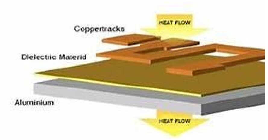
A Metal Core Printed Circuit Board (MCPCB) uses a metal base layer — most commonly aluminum, sometimes copper — to pull heat away from high-power components far more efficiently than a standard FR-4 board. The metal base sits beneath a thermally conductive dielectric and a standard copper circuit layer, giving you a direct thermal path from die to heat sink.
Where MCPCBs are used
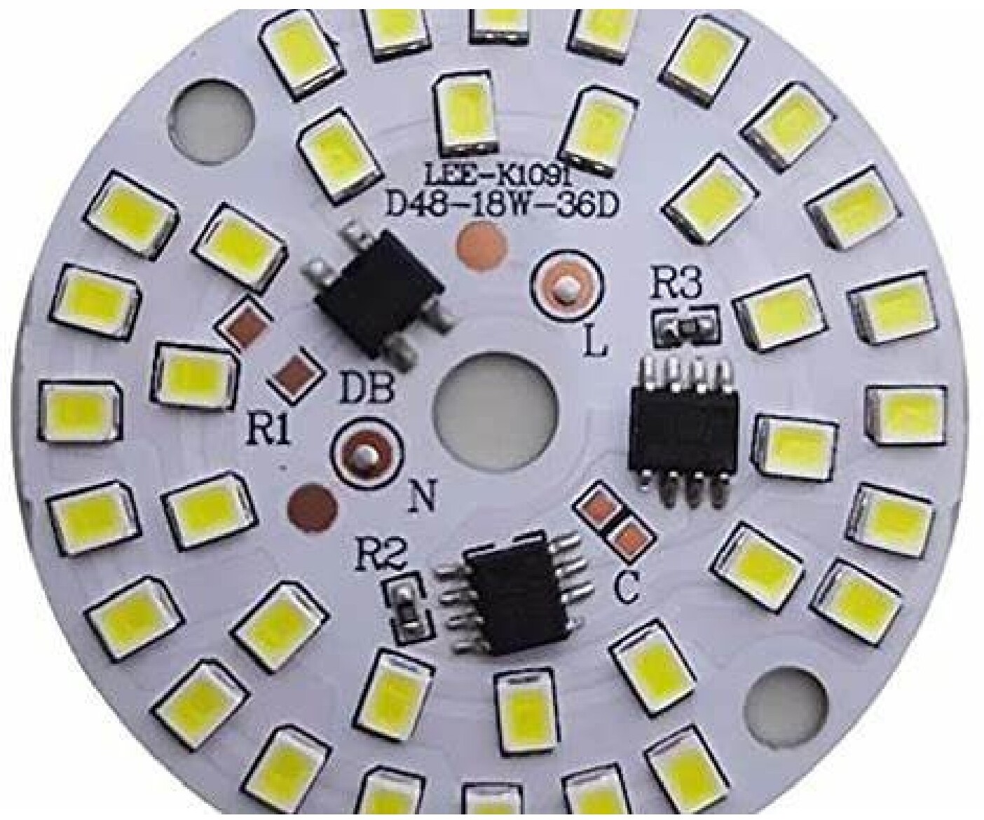
- LED lighting — high-brightness and high-power LED modules
- Power electronics — converters, inverters and motor drives
- Automotive — headlights, power modules and EV systems
- Industrial — power supplies and automation controls
- Consumer — power adapters and high-power devices
- Telecom — RF power amplifiers
Key benefits over standard FR-4
- Superior thermal management — lowers junction temperatures, extends component life and improves reliability.
- High power handling — designed for circuits with high current and power density that would damage FR-4.
- Mechanical stability — the metal base resists warping and survives vibration and thermal cycling.
- Compact designs — better heat dissipation lets you increase power density and shrink or eliminate external heatsinks.
- Higher LED density — designers can pack more LEDs per board because of the improved thermal path.
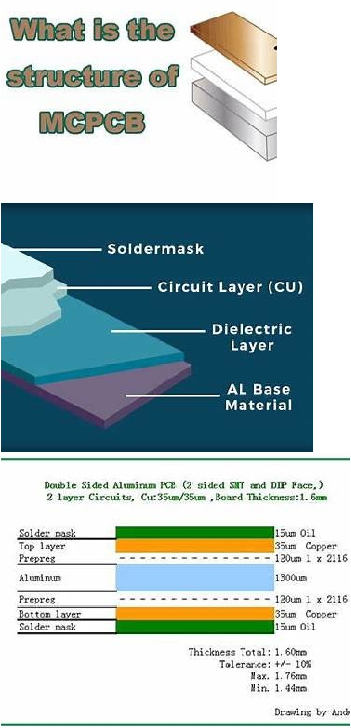
Basic MCPCB structure
| Layer | Description |
|---|---|
| Top layer | Copper circuitry — supports component mounting and signal routing |
| Middle layer | Thermally conductive dielectric — electrically insulating, thermally conductive |
| Bottom layer | Metal base (aluminum standard, copper for highest performance) |
Single-sided, double-sided and multilayer MCPCBs
MCPCBs are most commonly single-sided, but they don't have to be. As applications get more demanding we build several variants:
- Single-sided MCPCB — one copper layer over dielectric over the metal base. The standard for LED lighting and simple power circuits.
- Double-sided MCPCB — copper on both faces with the metal base bonded underneath as a heat spreader, or a metal core sandwiched between copper layers.
- Multilayer MCPCB — full multilayer stackups bonded to (or built around) a metal base for designs that need both routing density and aggressive thermal performance.
Example: double-sided aluminum MCPCB stackup
Two-layer circuit, 35 µm copper each side, 1.6 mm finished thickness (drawing by Andy):
| Layer | Material / Specification |
|---|---|
| Solder mask | 15 µm oil |
| Top layer | 35 µm copper |
| Prepreg | 120 µm — 1 × 2116 |
| Aluminum core | 1300 µm |
| Prepreg | 120 µm — 1 × 2116 |
| Bottom layer | 35 µm copper |
| Solder mask | 15 µm oil |
Total thickness: 1.60 mm · Tolerance: ±10% · Max 1.76 mm · Min 1.44 mm.
Embedded metal core builds
MCPCBs with pedestals
A newer substrate option mills the thin dielectric down to the bare metal base directly under the LED, letting the LED's thermal pad sit on a pedestal that contacts the heat sink with no dielectric in between. The result is an LED operating temperature drop of roughly 30 to 50 °C — a major reliability and lifetime improvement that's been adopted across the lighting industry.
Common materials
- Aluminum core — cost-effective, lightweight, the default choice for LEDs.
- Copper core — significantly higher thermal conductivity for the most demanding applications.
- Thermal dielectric — engineered epoxies or ceramic-filled systems; selection drives overall thermal performance.
- Copper foils — standard or heavy copper (3 oz to 10 oz+) for high-current designs, often combined with the metal core.
Manufacturing process
MCPCBs require specialized processing to protect the thin thermal dielectric while still delivering reliable copper circuitry. Our standard MCPCB flow:
- Metal base preparation
- Dielectric lamination
- Copper circuit imaging and etching
- Precision drilling and routing of the metal base
- Surface finish application
- Solder mask (where applicable)
- Electrical test and inspection
The hardest step is machining and drilling the aluminum or copper without tearing or distorting the very thin dielectric. Aluminum boards take roughly 10×longer to machine than standard FR-4, and copper-core boards up to 15× — one of the main cost drivers along with the proprietary thermal dielectric itself.
Design considerations
Thermal path optimization
- Minimize thermal resistance from component to metal core
- Use large copper areas and thermal vias where appropriate
Dielectric selection
- Balance thermal conductivity with electrical insulation
- Consider breakdown voltage and operating temperature
Component placement
- Place high-power components directly over the metal core
- Optimize spacing for heat spreading
Manufacturability
Bring us in early on stackup and material selection — it shortens lead time, controls cost and avoids surprises in machining the metal base.
MCPCB vs. standard FR-4
| Feature | Metal Core PCB | FR-4 PCB |
|---|---|---|
| Thermal conductivity | Excellent | Limited |
| Heat dissipation | Very high | Moderate |
| Power handling | High | Low to moderate |
| Mechanical strength | High | Moderate |
| Cost | Higher | Lower |
MCPCBs cost more up front, but they often reduce total system cost by eliminating large external heatsinks and improving long-term reliability.
MCPCB or heavy copper?
Need help on your build?
Talk to a Sunrise PCB engineer.